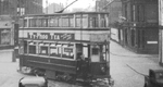
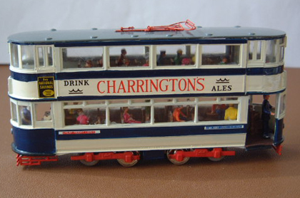
The Tenshodo motor with a 25.5mm wheelbase can be installed into the plastic tram kit with the minimum of modifications. The bogies in the kit can be modified to create an illusion that the tram has 8 wheels, but in fact there are only 4 wheels in contact with the track. The inspiration for this was taken from # John Howe’s video on the Kingsway subway. As I have no exact details of how John converted his tram kits I have therefore needed to develop my own method. I wanted to ensure that when the tram was fully finished I would still be able to service or replace the motor should the occasion arise.
# John Howe's Website http://londonmodeltramways.webs.com/
Tram Ground Floor
The ground floor o f the tram requires small chamfers (1.5mm x 60º) in each corner; this allows the floor to be glued 2.5mm higher than normal. Next, cut a rectangular hold in the floor (18.0mm x 8.0mm) to allow clearance with the motor fixing screw. The hole in the ground floor will also provide ventilation for the motor.
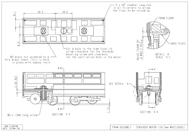
Fig 1 (Tram Ground Floor)
You will then need to find some suitable fixings- I used a M3 x 15mm long screw with M3 brass nuts. The two brass nuts were soldered to thin brass plate. These will be glued to the ground floor only when the base plate assembly is completed and screwed in place. This will then allow you to line everything up square and parallel. I also found it a good idea to mark the tram ground floor, bogies and base plate so they can always be put back together the right way round.
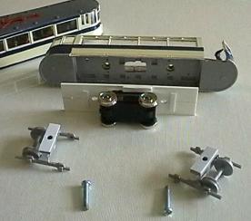
Dummy Bogies
Glue the bogie side frames to the base as shown in the assembly guide that comes with the kit. The top of the bogie base will need to be glued as shown in the diagram below and a 0.5mm styrene spacer glued on the top. Drill a clearance hole through the centre to allow the M3 x 15mm fixing screw to pass through freely.
Fig 2 (Dummy Bogies)
 |
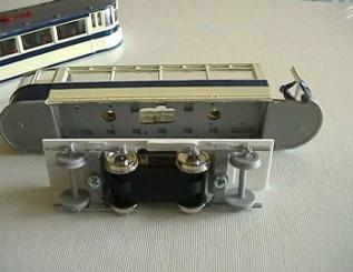 |
Fig 3 (Motor screwed to Base Plate) |
Fig 4 (Base Plate Assembly) |
Base Plate
The base plate is made from 1.5mm styrene, this requires a recess of 0.5mm deep to allow the motor body to sit flush. If you do not have a small milling machine handy this can be achieved by sandwiching two thicknesses of styrene together. Small strips of styrene are then used to make sure the motor and bogie assemblies remain square and parallel to the tram body.
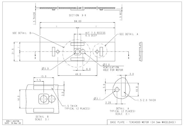
Fig 5 (Base Plate)
Click the links below to open either PDF
Adobe PDF Drawings (zipped)
E-Drawings of the above drawings are availble - Please email me for details

BACK TO TOP |